Airpreheater is a general term and represents any heater designed to heat air. It may be for residential use namely for room heating, house heating, etc. by means of gas, electricity or oil etc. In the present context reference is to the airpreheaters (Fossil_fuel_power_plant#Boiler_operation) used in steam generators (boilers) for generation of electricity in Power Generation Utilities.
The purpose of the air preheater is to recover the heat from the flue gas(exhaust gases) from the boiler to improve boiler efficiency. Incidentally the gases are sent to the chimney or stack at lowered temperature so that the design of the ducting and the stack becomes simplified. Also it controls the temperature of gases coming out of the stack.
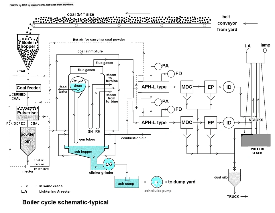
The location of the rotating type air preheater in the Boiler/TG cycle is shown in the typical schematic diagram.
Different types
For the use in Steam Generators (boilers)in Thermal_power_stations of Utility power stations, there are two types of design of the Airpreheaters. One is a tubular type built into the boiler outlet Flue_gas ducting and another one is of the regenerative type known as Ljungstrom (named after the name of inventor) [1] Regenerative Air Pre Heater(RAPH),a rotating type. This may be horizontal (now very common in power generation utilities) or vertical. [2]
Tubular type
Construction features
This consists of straight tube bundles located across outlet ducting of the boiler and open at both ends. The ends of each tube open outside of the ducting. Out side the tubes all around inside the ducting, the furnace hot gases pass through. . At one end of these tubes air from ducting of forced draft fan enters and at other end the hot air from inside of the tubes emerges into another hot air ducting. This hot air is carried by ducting to the boiler furnace for the combustion air requirement.
Problems
This construction is such that hot air for carrying powdered coal has to be a seperate arrangement, unlike in rotating types. Further due to dust laden abrasive flue gases the tubes outside the ducting wear out faster on the upstream side of the tubes. This calls for frequent replacement of tubes by cutting and welding, a time consuming process. Further the ductings for cold and hot air occupy additional space and structural supports. Therefore tubular type is not generally found now a days in bigger units of power generating utilities.
Ljungstrom (RAPH)
In this rotating type (RAPH) [3] the casing divides the same into two (bi sector type) or three (tri sector type) sectors by ducts connected to it. The seals on the casing and on the rotor divide the gas and air paths and the keep the gas/air leakages between the three sectors to minimum. Three sector types are very common now a days in power generation utilities. One half sector is connected by ducting to the boiler (hot) gas outlet and the corresponding outlet duct from the RAPH is connected by ducting for carrying lower temperature gases to the Dust collectors and then to the stack. The second sector, smaller than half size, is connected to the outlet of FD fan and that from other side ducting hot air is carried to boiler furnace, giving the main combustion air. The third sector, and of the smallest size, is connected to Primary fan outlet ducting and the other side is connected by ducting to take hot air for heating the air going to the pulverisers and to carry hot coal air mixture to boiler burners. The air from Primary air fan heated in the RAPH therefore acts as a heating air to remove the moisture from coal dust, acts as a carrier air for the pulversied coal from pulverisers to boiler burners and also as primary air for combustion. Typical RAPH is shown shown here. [4]
In view of this design, the rotor therefore, in every revolution, alternately is in the gas path and then in the air paths. Thus air preheater elements pick up the heat when on the furnace gas side and the air from FD fan and Primary air fan pick up the heat from heated elements when they are on their side, in every revolution. The rotor speed therefore is therefore kept very low at about 3 to 5 rpm only to give enough time for the airpreheater elements to pick up the heat and to give it to the ambient air from the FD and PA fans.
Construction features
The construction features are shown in Mitsubishi Regenerative Airpreheater diagram. [5]. In this design the whole air preheater casing is supported on the boiler supporting structure itself with necessary expansion joints in the ducting.
The vertical rotor of the same is supported on big thrust bearings at the lower side and has oil bath lubrication cooled by water circulating in the coils inside the oil bath. This arrangement is done for cooling of the shaft as this end of the vertical rotor is on the hot end of the ducting as well. The top end of the rotor has simple roller bearing to hold the rotating shaft in vertical position only.
The rotor is built up on the vertical shaft with radial supports and cages for holding the baskets in position. Radial and circumrential renewable seal plates are also provided to avoid leakages of gases or air between the sectors or between the duct and the casing, while in rotation.
For on line cleaning of the deposits from the baskets steam jets are provided such that the blown out dust and ash are colleted at the bottom ash hopper of the airpreheater. This dust hopper is connected for emptying along with main dust hoppers of dust collectors.
The rotor is turned at very low speed of 3 to 5 rpm by an air driven motor and gearing, as this requires to be started first before starting the boiler and also to be kept in rotation for some time after the boiler is stopped. (The air for this purpose is injected with lubricating oil, required for the air motor. The station air is generally totally dry as totally dry air required for the instrumentation.) This rotation is required before boiler starts and after boiler stops to avoid uneven expansion or warping of the rotor.
Necessary safety protected inspection windows are provided for internal viewing for its satisfactory operation under all operating conditions.
The baskets are in the sector housings provided on the rotor and are renewable. The life of the baskets depend on the ash abrasiveness and corrosiveness of the boiler outlet gases.
Problems
In this RAPH the dust laden and corrosive boiler gases have to pass between the elements of air preheater baskets. The elements are made up of zig zag corrugated plates pressed into a steel basket giving sufficient annular space in between for the gas to pass through. These plates are corrugated to give more surface area for the heat to be absorbed and also to give it the rigidity for stacking them into the baskets. The boiler flue gas also contains lot of dust particles (due to high ash content) not contributing towards combustion, such as silica, which is more abrasive. It may also contain corrosive gases depending on the composition of coal. The wear of the airpreheater elements depends on these factors. Indian Coals [6] are generally high in ash, sulphur and silica. The wear of the baskets therefore is generally more than other better coals. Hence frequent replacements are called for and new baskets are always kept ready. Early days Corten steel was being used for the elements. Today due to technological advance many manufacturers may use their own patents. Some manufacturers supply different materials for the use of the elements to lengthen the life of the baskets. [7]
In certain cases the unburnt deposits may occur on the air preheater elements causing it to catch fire during normal operations of the boiler giving rise to explosions inside the airpreheater. Some times mild explosions may be detected in the Control room by indication of the inlet and outlet temperatures of the combustion air.
External links
- http://www.asme.org/history/roster/H185.html
- http://www.mhi.co.jp/power/e_power/product/boiler/product/ah.html
- http://unitedfilter.com/index.php/default/merv-ratings
- http://pepei.pennnet.com/Articles/Article_Display.cfm?Section=ARTCL&ARTICLE_ID=235231&VERSION_NUM=1&p=6=Co
- http://www.osc.edu/research/pcrm/emissions/coal.shtml
| This page uses Creative Commons Licensed content from Wikipedia (view authors). | 
|