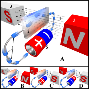
Hall effect diagram, showing electron flow (rather than conventional current).
Legend:
1. Electrons (not conventional current!)
2. Hall element, or Hall sensor
3. Magnets
4. Magnetic field
5. Power source
Description:
In drawing "A", the Hall element takes on a negative charge at the top edge (symbolised by the blue color) and positive at the lower edge (red color). In "B" and "C", either the electric current or the magnetic field is reversed, causing the polarization to reverse. Reversing both current and magnetic field (drawing "D") causes the Hall element to again assume a negative charge at the upper edge.
The Hall effect refers to the potential difference (Hall voltage) on opposite sides of a thin sheet of conducting or semiconducting material in the form of a 'Hall bar' or a van der Pauw element through which an electric current is flowing, created by a magnetic field applied perpendicular to the Hall element. The ratio of the voltage created to the amount of current is known as the Hall resistance, and is a characteristic of the material in the element. Dr. Edwin Hall discovered this effect in 1879.
Analysis[]
The Hall effect comes about due to the nature of the current flow in the conductor. Current consists of many small charge-carrying "particles" (typically electrons) which experience a force (called the Lorentz Force) due to the magnetic field. Some of these charge elements end up forced to the sides of the conductors, where they create a pool of net charge. This is only notable in larger conductors where the separation between the two sides is large enough.
One very important feature of the Hall effect is that it differentiates between positive charges moving in one direction and negative charges moving in the opposite. The Hall effect offered the first real proof that electric currents in metals are carried by moving electrons, not by protons. Interestingly enough, the Hall effect also showed that in some substances (especially semiconductors), it is more appropriate to think of the current as positive "holes" moving rather than negative electrons.
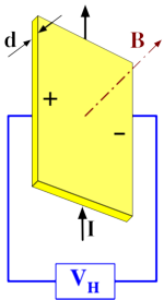
By measuring the Hall voltage across the element, one can determine the strength of the magnetic field applied. This can be expressed as

where VH is the voltage across the width of the plate, I is the current across the plate length, B is the magnetic field, d is the depth of the plate, e is the electron charge, and n is the bulk density of the carrier electrons.
So called Hall effect sensors are readily available from a number of different manufacturers, and may be used in various sensors such as fluid flow sensors, power sensors, and pressure sensors.
In the presence of large magnetic field strength and low temperature, one can observe the quantum Hall effect, which is the quantization of the Hall resistance.
In ferromagnetic materials (and paramagnetic materials in a magnetic field), the Hall resistivity includes an additional contribution, known as the Anomalous Hall Effect (or the Extraordinary Hall effect), which depends directly on the magnetization of the material, and is often much larger than the ordinary Hall effect. (Note that this effect is not due to the contribution of the magnetization to the total magnetic field.) Although a well-recognized phenomenon, there is still debate about its origins in the various materials. The anomalous Hall effect can be either an extrinsic (disorder-related) effect due to spin-dependent scattering of the charge carriers, or an intrinsic effect which can be described in terms of the Berry phase effect in the crystal momentum space (k-space).
Applications[]
Hall effect devices produce a very low signal level and thus require amplification. While suitable for laboratory instruments, the vacuum tube amplifiers available in the first half of the 20th century were too expensive, power consuming, and unreliable for everyday applications. It was only with the development of the low cost integrated circuit that the Hall effect sensor became suitable for mass application. Many devices now sold as "Hall effect sensors" are in fact a device containing both the sensor described above and a high gain integrated circuit (IC) amplifier in a single package. Reed switch electrical motors using the hall effect IC is another application.
Advantages over other methods[]
Hall effect devices when appropriately packaged are immune to dust, dirt, mud, and water. These characteristics make Hall effect devices better for position sensing than alternative means such as optical and electromechanical sensing.
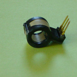
Hall effect current sensor with internal integrated circuit amplifier. 8mm opening. Zero current output voltage is midway between the supply voltages that maintain a 4 to 8 volt differential. Non-zero current response is proportional to the voltage supplied and is linear to 60 amperes for this particular (25 A) device.
When electrons flow through a conductor, a magnetic field is produced. Thus, it is possible to create a non-contacting current sensor. The device has three terminals. A sensor voltage is applied across two terminals and the third provides a voltage proportional to the current being sensed. This has several advantages; no resistance (a "shunt") need be inserted in the primary circuit. Also, the voltage present on the line to be sensed is not transmitted to the sensor, which enhances the safety of measuring equipment.
The range of a given feedthrough sensor may be extended upward and downward by appropriate wiring. To extend the range to lower currents, multiple turns of the current-carrying wire may be made through the opening. To extend the range to higher currents, a current divider may be used. The divider splits the current across two wires of differing widths and the thinner wire, carrying a smaller proportion of the total current, passes through the sensor.
Split ring clamp-on sensor[]
A variation on the ring sensor uses a split sensor which is clamped onto the line enabling the device to be used in temporary test equipment. If used in a permanent installation, a split sensor allows the electrical current to be tested without dismantling the existing circuit.
Analog multiplication[]
The output is proportional to both the applied magnetic field and the applied sensor voltage. If the magnetic field is applied by a solenoid, the sensor output is proportional to product of the current through the solenoid and the sensor voltage. As most applications requiring computation are now performed by small (even tiny) digital computers, the remaining useful application is in power sensing, which combines current sensing with voltage sensing in a single Hall effect device.
Power sensing[]
By sensing the current provided to a load and using the device's applied voltage as a sensor voltage it is possible to determine the power flowing through a device. This power is (for direct current devices) the product of the current and the voltage. With appropriate refinement the devices may be applied to alternating current applications where they are capable of reading the true power produced or consumed by a device.
Position and motion sensing[]
Hall effect devices used in motion sensing and motion limit switches can offer enhanced reliability in extreme environments. As there are no moving parts involved within the sensor or magnet, typical life expectancy is improved compared to traditional electromechanical switches. Additionally, the sensor and magnet may be encapsulated in an appropriate protective material.
Automotive ignition and fuel injection[]
If the magnetic field is provided by a rotating magnet resembling a toothed gear, an output pulse will be generated each time a tooth passes the sensor. This is used in modern automotive primary distributor ignition systems, replacing the earlier "breaker" points (which were prone to wear and required periodic adjustment and replacement). Similar sensor signals are used to control multi-port sequential fuel injection systems, where each cylinder's intake runner is fed fuel from an injector consisting of a spray valve regulated by a solenoid. The sequences are timed to match the intake valve openings and the duration of each sequence (controlled by a computer) determines the amount of fuel delivered.
Wheel rotation sensing[]
The sensing of wheel rotation is especially useful in anti-lock brake systems. The principles of such systems have been extended and refined to offer more than anti-skid functions, now providing extended vehicle "handling" enhancements.
The Corbino effect[]
The Corbino effect is a phenomenon based on the Hall effect, but a disk-shaped metal sample is used in place of a rectangular one.
See also[]
- Capacitor
- Elementary charge
- Frank Wilczek
- Hall effect thruster
- Nernst effect
- Nernst-Ettinghausen effect
- Quantum Hall effect
- Thermal Hall effect
- Transducer
- Van der Pauw method
External links and references[]
- "The Hall Effect". nist.gov.
- Hall, Edwin, "On a New Action of the Magnet on Electric Currents". American Journal of Mathematics vol 2 1879.
| This page uses Creative Commons Licensed content from Wikipedia (view authors). | 
|