A capacitor is a device that stores energy in the electric field created between a pair of conductors on which equal, but opposite, electric charges have been placed. A capacitor is occasionally referred to using the older term condenser.
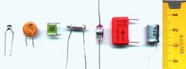
Various types of capacitors
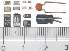
SMD capacitors: electrolytic at the bottom line, ceramic above them; through-hole ceramic and electrolytic capacitors at the right side for comparison
History[]
See [1]
Physics[]
Overview[]
A capacitor consists of two electrodes or plates, each of which stores an opposite charge. These two plates are conductive and are separated by an insulator or dielectric. The charge is stored at the surface of the plates, at the boundary with the dielectric. Because each plate stores an equal but opposite charge, the total charge in the capacitor is always zero.
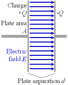
When electric charge accumulates on the plates, an electric field is created in the region between the plates that is proportional to the amount of accumulated charge. This electric field creates a potential difference V = E·d between the plates of this simple parallel-plate capacitor.
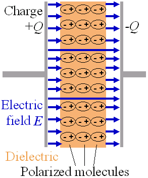
The electrons in the molecules move or rotate the molecule toward the positively charged left plate. This process creates an opposing electric field that partially annuls the field created by the plates. (The air gap is shown for clarity; in a real capacitor, the dielectric is in direct contact with the platese.)
Capacitance[]
The capacitor's capacitance (C) is a measure of the amount of charge (Q) stored on each plate for a given potential difference or voltage (V) which appears between the plates:

In SI units, a capacitor has a capacitance of one farad (F) when one coulomb (C) of charge causes a potential difference of one volt (V) across the plates. Since the farad is a very large unit, values of capacitors are usually expressed in microfarads (µF) x10−6, nanofarads (nF) x10−9 or picofarads (pF) x10−12.
The capacitance is proportional to the surface area of the conducting plate and inversely proportional to the distance between the plates. It is also proportional to the permittivity of the dielectric (that is, non-conducting) substance that separates the plates.
The capacitance of a parallel-plate capacitor is given by:

where ε is the permittivity of the dielectric, A is the area of the plates and d is the spacing between them.
Stored energy[]
As opposite charges accumulate on the plates of a capacitor due to the separation of charge, a voltage develops across the capacitor owing to the electric field of these charges. Ever increasing work must be done against this ever increasing electric field as more charge is separated. The energy (measured in joules, in SI) stored in a capacitor is equal to the amount of work required to establish the voltage across the capacitor, and therefore the electric field. The energy stored is given by:

where V is the voltage across the capacitor.
Hydraulic model[]
As electrical circuitry can be modeled by fluid flow, a capacitor can be modeled as a chamber with a flexible diaphragm separating the input from the output. As can be determined intuitively as well as mathematically, this provides the correct characteristics: the pressure across the unit is proportional to the integral of the current, a steady-state current cannot pass through it but a pulse or alternating current can be transmitted, the capacitance of units connected in parallel is equivalent to the sum of their individual capacitance; etc.
In electric circuits[]
Circuits with DC sources[]
Electrons cannot directly pass across the dielectric from one plate of the capacitor to the other. When there is a current through a capacitor, electrons accumulate on one plate and electrons are removed from the other plate. This process is commonly called 'charging' the capacitor even though the capacitor is at all times electrically neutral. In fact, the current through the capacitor results in the separation rather than the accumulation of electric charge. This separation of charge causes an electric field to develop between the plates of the capacitor giving rise to voltage across the plates. This voltage V is directly proportional to the amount of charge separated Q. But Q is just the time integral of the current I through the capacitor. This is expressed mathematically as:

where
- I is the current flowing in the conventional direction, measured in amperes
- C is the capacitance in farads
For circuits with a constant (DC) voltage source, the voltage across the capacitor cannot exceed the voltage of the source. Thus, an equilibrium is reached where the voltage across the capacitor is constant and the current through the capacitor is zero. For this reason, it is commonly said that capacitors block DC current.
Circuits with AC sources[]
The capacitor current due to an AC voltage or current source reverses direction periodically. That is, the AC current alternately charges the plates in one direction and then the other. With the exception of the instant that the current changes direction, the capacitor current is non-zero at all times during a cycle. For this reason, it is commonly said that capacitors 'pass' AC current. However, at no time do electrons actually cross between the plates.
Since the voltage across a capacitor is the integral of the current, as shown above, with sine waves in AC or signal circuits this results in a phase difference of 90 degrees, the current leading the voltage phase angle. It can be shown that the AC voltage across the capacitor is in quadrature with the AC current through the capacitor. That is, the voltage and current are 'out-of-phase' by a quarter cycle. The amplitude of the voltage depends on the amplitude of the current divided by the product of the frequency of the current with the capacitance, C. The ratio of the voltage amplitude to the current amplitude is called the reactance of the capacitor. This capacitive reactance is given by:

where
- , the angular frequency measured in radians per second
- XC = capacitive reactance, measured in ohms
- f = frequency of AC in hertz
- C = capacitance in farads

and is analogous to the resistance of a resistor. Clearly, the reactance is inversely proportional to the frequency. That is, for very high-frequency alternating currents the reactance approaches zero so that a capacitor is nearly a short circuit to a very high frequency AC source. Conversely, for very low frequency alternating currents, the reactance increases without bound so that a capacitor is nearly an open circuit to a very low frequency AC source.
Reactance is so called because the capacitor doesn't dissipate power, but merely stores energy. In electrical circuits, as in mechanics, there are two types of load, resistive and reactive. Resistive loads (analogous to an object sliding on a rough surface) dissipate energy that enters them, ultimately by electromagnetic emission (see Black body radiation), while reactive loads (analogous to a spring or frictionless moving object) retain the energy.
The impedance of a capacitor is given by:

where and is the imaginary unit [3].

Hence, capacitive reactance is the negative imaginary component of impedance. The negative sign indicates that the current leads the voltage by 90° for a sinusoidal signal, as opposed to the inductor, where the current lags the voltage by 90°.
Also significant is that the impedance is inversely proportional to the capacitance, unlike resistors and inductors for which impedances are linearly proportional to resistance and inductance respectively. This is why the series and shunt impedance formulae (given below) are the inverse of the resistive case. In series, impedances sum. In shunt, conductances sum.
In a tuned circuit such as a radio receiver, the frequency selected is a function of the inductance (L) and the capacitance (C) in series, and is given by:

This is the frequency at which resonance occurs in an RLC series circuit.
For an ideal capacitor, the capacitor current is proportional to the time rate of change of the voltage across the capacitor where the constant of proportionality is the capacitance, C:

The impedance in the frequency domain can be written as
- .

This shows that a capacitor has a high impedance to low-frequency signals (when ω is small) and a low impedance to high-frequency signals (when ω is large). This frequency dependent behaviour accounts for most uses of the capacitor (see "Applications", below).
When using the Laplace transform [4] in circuit analysis, the capacitive impedance is represented in the s domain by:

Capacitors and displacement current[]
The physicist James Clerk Maxwell [5] invented the concept of displacement current, dD/dt, to make Ampere's law consistent with conservation of charge in cases where charge is accumulating as in a capacitor. He interpreted this as a real motion of charges, even in vacuum, where he supposed that it corresponded to motion of dipole [6] charges in the luminiferous aether [7]. Although this interpretation has been abandoned, Maxwell's correction to Ampere's law remains valid.
Capacitor networks[]
A capacitor can be used to block the DC Current flowing within the circuit and therefore have important applications in coupling of ac signals between amplifier stages, whilst preventing dc from passing.
Series or parallel arrangements[]
- Main article: Series and parallel circuits
Capacitors in a parallel configuration each have the same potential difference (voltage). Their total capacitance (Ceq) is given by:


The current through capacitors in series stays the same, but the voltage across each capacitor can be different. The sum of the potential differences (voltage) is equal to the total voltage. Their total capacitance is given by:

In parallel, the total charge stored is the sum of the charge in each capacitor. While in series, the charge on each capacitor is the same.
One possible reason to connect capacitors in series is to increase the overall voltage rating. In practice, a very large resistor might be connected across each capacitor to ensure that the total voltage is divided appropriately for the individual ratings, rather than by minute differences in the capacitance values. Another application is for use of polarized capacitors in alternating current circuits; the capacitors are connected in series, in reverse polarity, so that at any given time one of the capacitors is not conducting.
Capacitor/inductor duality[]
In mathematical terms, the ideal capacitor can be considered as an inverse of the ideal inductor, because the voltage-current equations of the two devices can be transformed into one another by exchanging the voltage and current terms. Just as two or more inductors can be magnetically coupled to make a transformer, two or more charged conductors can be electrostatically coupled to make a capacitor. The mutual capacitance of two conductors is defined as the current that flows in one when the voltage across the other changes by unit voltage in unit time.
Applications[]
| Capacitor | Polarized capacitors |
Variable capacitor |
|---|---|---|
Capacitors have many uses in electronic and electrical systems.
Energy storage[]
A capacitor can store electric energy when disconnected from its charging circuit, so it can be used like a temporary battery. The recent commercial availability of very large value capacitors, one farad in size and larger, has enabled such components to allow batteries to be changed in electronic devices without the memory being lost, for instance, or for energy storage for delivery during extreme peak demands, as often found in the enormously powerful car audio systems now seen.
Signal processing[]
The energy stored in a capacitor can be used to represent information, either in binary form, as in computers, or in analogue form, as in switched-capacitor circuits and bucket-brigade delay lines. Capacitors can be used in analog circuits as components of integrators or more complex filters and in negative feedback loop stabilization. Signal processing circuits also use capacitors to integrate a current signal.
Power supply applications[]
Capacitors are commonly used in power supplies where they smooth the output of a full or half wave rectifier. They can also be used in charge pump circuits as the energy storage element in the generation of higher voltages than the input voltage. Capacitors are connected in parallel with the power circuits of most electronic devices and larger systems (such as factories) to shunt away and conceal current fluctuations from the primary power source to provide a "clean" power supply for signal or control circuits. Audio equipment, for example, uses several capacitors in this way, to shunt away power line hum before it gets into the signal circuitry. The capacitors act as a local reserve for the DC power source, and bypass AC currents from the power supply.
Capacitors are used in power factor correction. Such capacitors often come as three capacitors connected as a three phase load. Usually, the values of these capacitors are given not in farads but rather as a reactive power in volt-amperes reactive (VAr). The purpose is to match the inductive loading of machinery which contains motors, to make the load appear to be mostly resistive.
Capacitors are also used in parallel to interrupt units of a high-voltage circuit breaker in order to distribute the voltage between these units. In this case they are called grading capacitors. In schematic diagrams, a capacitor used primarily for DC charge storage is often drawn vertically in circuit diagrams with the lower, more negative, plate drawn as an arc. The straight plate indicates the positive terminal of the device, if it is polarized (see electrolytic capacitor).
Non-polarized electrolytic capacitors used for signal filtering are typically drawn with two curved plates. Other non-polarized capacitors are drawn with two straight plates.
Tuned circuits[]
Capacitors and inductors are applied together in tuned circuits to select information in particular frequency bands. For example, radio receivers rely on variable capacitors to tune the station frequency. Speakers use passive analog crossovers, and analog equalizers use capacitors to select different audio bands.
Signal coupling[]
Because capacitors pass AC but block DC signals (when charged up to the applied DC voltage), they are often used to separate the AC and DC components of a signal. This method is known as AC coupling. (Sometimes transformers are used for the same effect.) Here, a large value of capacitance, whose value need not be accurately controlled, but whose reactance is small at the signal frequency, is employed. Capacitors for this purpose designed to be fitted through a metal panel are called feed-through capacitors, and have a slightly different schematic symbol.
Noise filters, motor starters, and snubbers[]
When an inductive circuit is opened, the energy stored in the magnetic field of the inductance collapses quickly, creating a large voltage across the open circuit of the switch or relay. If the inductance is large enough, the energy will generate a spark, causing the contact points to oxidize, deteriorate, or sometimes weld together, or destroying a solid-state switch. A snubber capacitor across the newly opened circuit creates a path for this impulse to bypass the contact points, thereby preserving their life; these were commonly found in contact breaker ignition systems, for instance. Similarly, in smaller scale circuits, the spark may not be enough to damage the switch but will still radiate undesirable radio frequency interference (RFI), which a filter capacitor absorbs. Snubber capacitors are usually employed with a low-value resistor in series, to dissipate energy more slowly and minimize RFI. Such resistor-capacitor combinations are available in a single package.
In an inverse fashion, to initiate current quickly through an inductive circuit requires a greater voltage than required to maintain it; in uses such as large motors, this can cause undesirable startup characteristics, and a motor starting capacitor is used to store enough energy to give the current the initial push required to start the motor up.
Transducer applications[]
Although capacitors usually maintian a fixed physical structure and utilization varies the electrical voltage and current, the effects of varying the physical and/or electrical characteristics of the dielectric with a fixed electrical supply can also be of use. Capacitors with an exposed and porous dielectric can be used to measure humidity in air. Capacitors with a flexible plate can be used to measure strain or pressure. Capacitors are used as the transducer in condenser microphones, where one plate is moved by air pressure, relative to the fixed position fo the other plate.
Accelerometers[]
Some accelerometers use MEMS capacitors etched on a chip to measure the magnitude and direction of the acceleration vector. They are used to detect changes in acceleration, eg. as tilt sensors or to detect free fall, as sensors triggering airbag deployment, and in many other applications.
Weapons applications[]
An obscure military application of the capacitor is in an EMP weapon. A plastic explosive is used for the dielectric. The capacitor is charged up and the explosive is detonated. The capacitance becomes smaller, but the charge on the plates stays the same. This creates a high-energy electromagnetic shock wave capable of destroying unprotected electronics for miles around.
Ideal and non ideal capacitors[]
In practice, this ideal model of the capacitor often has to be modified to reflect real world capacitor construction and operation. The most obvious example is electrolytic capacitors, where the capacitor is polarized such that when the voltage is connected in reversed fashion, the capacitor acts as a resistor. Similar problems of dielectric leakage are a constant complication of all capacitor design however, and have led to constant improvements in capacitor design, as the material used for dielectrics has changed from oiled paper to mylar and from ceramic to Teflon. This also addresses the related problem of dielectric stability; oiled or electrolyte soaked paper dries out over time, reducing the capacitance and increasing leakage, a problem reduced in modern components.
On the other hand, the requirements of large plate area for reasonably useful capacitor values as well as reasonable packaging resulted in the universal practice of rolling the plate/dielectric sandwich into a cylinder, which was then encapsulated. However, this process also creates an inductance in series with the capacitance, just as introducing a coiled wire of similar characteristics in series with the flat capacitor would; in sensitive circuits, this inductance must be taken into account, either by using a capacitor designed to have lower inductance, or by bypassing a large capacitor with a smaller, noninductive one. This practice has become more common in audiophile-oriented products recently, as inductive problems in low-cost capacitors were demonstrated to degrade high-frequency fidelity.
Computers and cell (mobile) phones use surface-mount stacked capacitors, since these devices have no leads and therefore no lead inductance. When the capacitor plates are mounted at right-angles to the ciruit board, the inductance can be made extremely low. To further reduce inductance, wide conductor traces and small gaps are used and the capacitor is shaped accordingly.
Dielectric materials can produce unwanted side effects. For example, the dielectric constant of barium titanate [8] used in ceramic capacitors changes with temperature and pressure. Such capacitors are sensitive to vibration and flexing, and can cause a type of signal modulation in electronic circuits called microphonics.
Capacitor hazards and safety[]
Capacitors may retain a charge long after power is removed from a circuit; this charge can cause shocks (up to and including electrocution) or damage to connected equipment. Since capacitors have such low equivalent series resistances (ESRs), they have the capacity to deliver large currents into short circuits; this can be dangerous. Care must be taken to ensure that any large or high-voltage capacitor is properly discharged before servicing the containing equipment. For safety purposes, all large capacitors should be discharged before handling. For board-level capacitors, this is done by placing a bleeder resistor across the terminals, whose resistance is large enough that the leakage current will not affect the circuit, but small enough to discharge the capacitor shortly after power is removed. High voltage capacitors should be stored with the terminals shorted to dissipate any stored charge.
Large oil-filled old capacitors must be disposed of properly as some contain polychlorinated biphenyls [9](PCBs). It is known that waste PCBs can leak into groundwater under landfills. If consumed by drinking contaminated water, PCBs are carcinogenic [10], even in very tiny amounts. If the capacitor is physically large it is more likely to be dangerous and may require precautions in addition to those described above. New electrical components are no longer produced with PCBs. Disambiguation: Please keep in mind that PCB in electronics usually means Printed Circuit Board, unlike in chemistry where it may be used as seen above.
See also[]
Capacitor (component) Template:Wikibookspar
- Capacitance
- Capacitor plague capacitor failures on computer motherboards
- Circuit design
- Electromagnetism
- Electricity
- Electronics
- Inductor
- Practical capacitors
- Supercapacitor
External links[]
- Practical Capacitors and other Electronics for Robotics
- Caltech: Practical capacitor properties
- General Atomics Electronic Systems, inc. High Voltage Pulsed Power Capacitors and Systems.
- Skeleton NanoLab, Research & Development of advanced capacitors
- Howstuffworks.com: How Capacitors Work
- CapSite 2016: Introduction to Capacitors
- AC circuits
References[]
"IEEE Spectrum", January, 2005 Vol 42, No. 1, North American Edition.
- "The ARRL Handbook for Radio Amateurs, 68th ed", The Amateur Radio Relay League, Newington CT USA, 1991
- "Basic Circuit Theory with Digital Computations", Lawrence P. Huelsman, Prentice-Hall, 1972
- Philosophical Transactions of the Royal Society LXXII, Appendix 8, 1782 (Volta coins the word condenser)
- A. K. Maini "Electronic Projects for Beginners", "Pustak Mahal", 2nd Edition: March, 1998 (INDIA [11])
- Spark Museum (von Kleist and Musschenbroek)
- Biography of von Kleist
| This page uses Creative Commons Licensed content from Wikipedia (view authors). | 
|