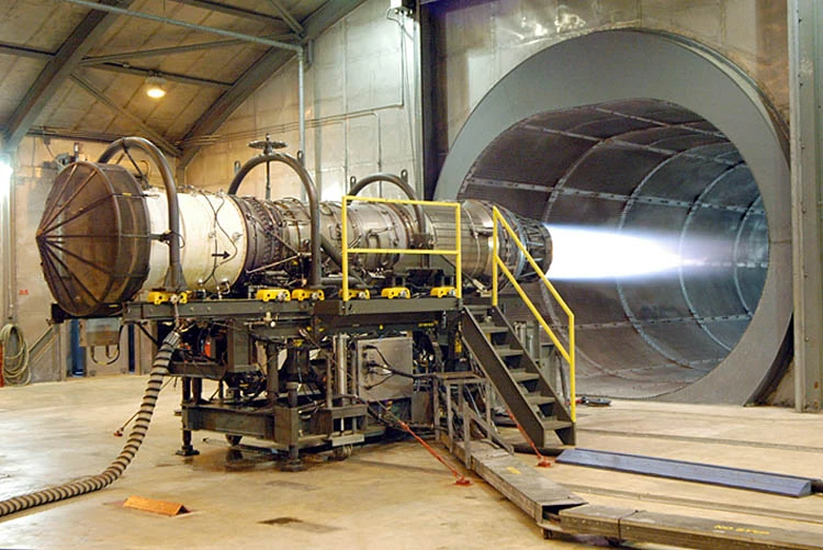
A Pratt and Whitney turbofan engine for the F-15 Eagle is tested at Robins Air Force Base, Georgia, USA. The tunnel behind the engine muffles noise and allows exhaust to escape. The mesh cover at the front of the engine (left of photo) prevents debris—or people—from being pulled into the engine by the huge volume of air rushing into the inlet.
A jet engine is any engine that accelerates and discharges a fast moving jet of fluid to generate thrust in accordance with Newton's third law of motion. This broad definition of jet engines includes turbojets, turbofans, turboprops, rockets and ramjets, but in common usage, the term generally refers to a gas turbine used to produce a jet of high speed exhaust gases for propulsive purposes.[]
Turbojet engines[]
A turbojet engine is a type of internal combustion engine often used to propel aircraft. Air is drawn into the rotating compressor via the intake and is compressed to a higher pressure before entering the combustion chamber. Fuel is mixed with the compressed air and ignited by flame in the eddy of a flame holder. This combustion process significantly raises the temperature of the gas. Hot combustion products leaving the combustor expand through the turbine, where power is extracted to drive the compressor. Although this expansion process reduces both the gas temperature and pressure at exit from the turbine, both parameters are usually still well above ambient conditions. The gas stream exiting the turbine expands to ambient pressure via the propelling nozzle, producing a high velocity jet in the exhaust plume. If the jet velocity exceeds the aircraft flight velocity, there is a net forward thrust upon the airframe.
Under normal circumstances, the pumping action of the compressor prevents any backflow, thus facilitating the continuous flow process of the engine. Indeed, the entire process is similar to a four-stroke cycle, but with induction, compression, ignition, expansion and exhaust taking place simultaneously. The efficiency of a jet engine is strongly dependent upon the Overall Pressure Ratio (Combustor Entry Pressure/Intake Delivery Pressure) and the Turbine Inlet Temperature of the cycle.
It is also perhaps instructive to compare turbojet engines with propeller engines. Turbojet engines take a relatively small mass of air and accelerate it by a large amount, whereas a propeller takes a large mass of air and accelerates it by a small amount. The high-speed exhaust of a jet engine makes it efficient at high speeds (especially supersonic speeds) and high altitudes. On slower aircraft and those required to fly short stages, a gas turbine-powered propeller engine, commonly known as a turboprop, is more common and much more efficient. Very small aircraft generally use conventional piston engines to drive a propeller but small turboprops are getting smaller as engineering technology improves.
The turbojet described above is a single spool design, where a single shaft connects the turbine to the compressor. Higher Overall Pressure Ratio designs often have two concentric shafts, to improve compressor stability during engine throttle movements. The outer (HP) shaft connects the High Pressure (HP) Compressor to the HP turbine. This HP Spool, with the combustor, forms the core or gas generator of the engine. The inner shaft connects the Low Pressure (LP) Compressor to the LP Turbine to create the LP Spool. Both spools are free to operate at their optimum shaft speed.
Turbofan engines[]
Most modern jet engines are actually turbofans, where the LP Compressor acts as a fan, supplying supercharged air to not only the engine core, but to a bypass duct. The bypass airflow either passes to a separate Cold Nozzle or mixes with LP Turbine exhaust gases, before expanding through a Mixed Flow Nozzle.
Forty years ago there was little difference between civil and military jet engines, apart from the use of afterburning in some (supersonic) applications.
Civil turbofans, today, have a low specific thrust (net thrust/airflow) to keep jet noise to a minimum and to improve fuel efficiency. Consequently the bypass ratio (bypass flow/core flow) is relatively high (usually much greater than 3.0). Only a single fan stage is required, because a low specific thrust implies a low fan pressure ratio.
Today's military turbofans, however, have a relatively high specific thrust, to maximize the thrust for a given frontal area, jet noise being of little consequence. Multi-stage fans are normally required to achieve the relatively high fan pressure ratio needed for a high specific thrust. Although high Turbine Inlet Temperatures are frequently employed, the bypass ratio tends to be low (usually significantly less than 2.0).
An approximate equation for calculating the net thrust of a jet engine is:
- Fnet = m(vjfe - va )
where:
- m = intake mass flow
- vjfe = fully expanded jet velocity (in the exhaust plume)
- va = aircraft flight velocity
While the m·vjfe term represents the gross thrust of the nozzle, the m·va term represents the ram drag of the intake. Most types of jet engine have an air intake, which provides the bulk of the gas exiting the exhaust. There is, however, a penalty for picking this air up and this is known as the ram drag. Conventional rocket motors, however, do not have an air intake, the oxidizer being carried within the airframe. Consequently, rocket motors do not have ram drag; the gross thrust of the nozzle is the net thrust of the engine. Consequently, the thrust characteristics of a rocket motor are completely different from that of an air breathing jet engine; at full throttle, the thrust of a rocket motor improves slightly with increasing altitude (because the back pressure from the atmosphere falls), whereas with a turbojet (or turbofan) the falling density of the air entering the intake causes the net thrust to decrease with increasing altitude.
History[]
Before the advent of the jet engine, the reciprocating piston engine in its different forms (rotary and static radial, aircooled and liquid-cooled inline) had been the only type of powerplant available to aircraft designers. This was understandable so long as low aircraft performance parameters were considered acceptable, and indeed inevitable. However, by approximately the late 1930s, engineers were beginning to realize that conceptually the piston engine was self-limiting in terms of the maximum performance which could be obtained from it; the limit was essentially one of propeller efficiency, which seemed to peak as blade tips approached supersonic tangential velocity. If engine, and thus aircraft, performance were ever to increase beyond such a barrier, a way would have to be found to radically improve the design of the piston engine, or a wholly new type of powerplant would have to be conceived. The latter would prove to be the case. The gas turbine (turbojet, or simply jet) engine, as subsequently developed, would become almost as revolutionary to aviation as the Wright brothers' 2nd
first flight.
The gas turbine was not an idea developed in the 1930s: the patent for a stationary turbine was granted to John Barber in England in 1791. The earliest attempts at jet engines were hybrid designs in which an external power source supplied the compression. In this system (called a thermojet by Secondo Campini) the air is first compressed by a fan driven by a conventional piston engine, then it is mixed with fuel and burned for jet thrust. The examples of this type of design were the Henri Coanda's Coanda-1910 aircraft, and the much later Campini Caproni CC.2, and the Japanese Tsu-11 engine intended to power Ohka kamikaze planes towards the end of World War II. None were entirely successful and the CC.2 ended up being slower than the same design with a traditional engine and propeller combination.
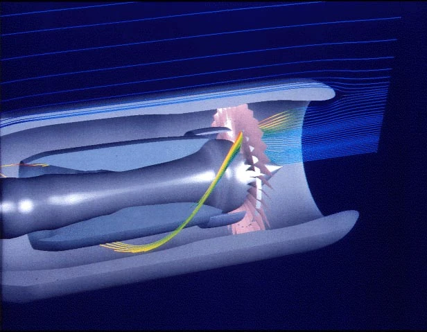
Jet engine airflow simulation
The key to the useful jet engine was the gas turbine, used to extract energy to drive the compressor from the engine itself. The first gas turbine to successfully run self-sustaining was built in 1903 by Norwegian engineer Aegidius Elling. The first patents for jet propulsion were issued in 1917. Limitations in design and practical engineering and metallurgy prevented such engines reaching manufacture. The main problems were safety, reliability, weight and, especially, sustained operation.
On January 16, 1930, in England, Frank Whittle submitted patents for his own design for a full-scale aircraft engine (granted in 1932). In 1935 Hans von Ohain started work on a similar design in Germany, seemingly unaware of Whittle's work.
Ohain approached Ernst Heinkel, one of the larger aircraft industrialists of the day, who immediately saw the promise of the design. Heinkel had recently purchased the Hirth engine company, and Ohain and his master machinist Max Hahn were set up there as a new division of the Hirth company. They had their first HeS 1 engine running by September 1937. Unlike Whittle's design, Ohain used hydrogen as fuel, which he credits for the early success. Their subsequent designs culminated in the gasoline-fuelled HeS 3 of 1,100 lbf (5 kN), which was fitted to Heinkel's simple and compact He 178 airframe and flown by Erich Warsitz in the early morning of August 27, 1939, from Marienehe aerodrome, an impressively short time for development. The He 178 was the world's first jetplane.
In England, Whittle had significant problems in finding funding for research, and the Air Ministry largely ignored it while they concentrated on more pressing issues. Using private funds he was able to get a test engine running in 1937, but this was very large and unsuitable for use in an aircraft. By 1939 work had progressed to the point where the engine was starting to look useful, and Whittle's Power Jets Ltd. started receiving Air Ministry money. In 1941 a flyable version of the engine called the W.1, capable of 1000 lbf (4 kN) of thrust, was fitted to the Gloster E28/39 airframe, and first flew on May 15, 1941 at RAF Cranwell.
One problem with both of these early designs, which are called centrifugal-flow engines, was that the compressor works by "throwing" (accelerating) air outward from the central intake to the outer periphery of the engine where the air is then compressed by a divergent duct setup—converting velocity into pressure. The advantage was that such compressor designs were well understood in centrifugal superchargers but this leads to a very large cross section for the engine at rotational speeds that were usable at the time. A disadvantage was that the air flow had to be "bent" to flow rearwards through the combustion section and to the turbine and tailpipe. With improvements to bearings, the shaft speed of the engine would increase and the diameter of the centrifugal compressor would reduce greatly. The shortness of this engine is an advantage. The strength of this type of compressor is an advantage over the later axial-flow compressors that are still liable to foreign object damage (FOD in aviation parlance).
Austrian Anselm Franz of Junkers' engine division (Junkers Motoren or Jumo) addressed this problem with the introduction of the axial-flow compressor. Essentially, this is a turbine in reverse. Air coming in the front of the engine is blown to the rear of the engine by a fan stage (convergent ducts), where it is crushed against a set of non-rotating blades called stators (divergent ducts). The process is nowhere near as powerful as the centrifugal compressor, so a number of these pairs of fans and stators are placed in series to get the needed compression. Even with all the added complexity, the resulting engine is much smaller in diameter. Jumo was assigned the next engine number, 4, and the result was the Jumo 004 engine. After many lesser technical difficulties were solved, mass production of this engine started in 1944 as a powerplant for the world's first jet-fighter aircraft, the Messerschmitt Me 262. Because Hitler wanted a new bomber the Me 262 came too late to decisively impact Germany's position in World War II, but it will be remembered as the first use of jet engines in service. After the end of the war the German Me 262 aircraft were extensively studied by the victorious allies and contributed to work on early Soviet and US jet fighters.
British engines also were licensed widely in the US (see Tizard Mission). Their most famous design, the Nene would also power the USSR's jet aircraft also after a technology exchange. American designs would not come fully into their own until the 1960s.
Types[]
There are a large number of types of jet engines, which get propulsion from a high speed exhaust jet. Some examples are as follows:
| Type | Description | Advantages | Disadvantages |
| Water jet | Squirts water out the back of a boat | Can run in shallow water, powerful, less harmful to wildlife | Can be less efficient than a propeller |
| Thermojet | Most primitive airbreathing jet engine | Very inefficient and underpowered | |
| Turbojet | Generic term for simple turbine engine | Simplicity of design | Basic design, misses many improvements in efficiency and power |
| Turbofan | Power tapped off exhaust used to drive bypass fan | Quieter due to greater mass flow and lower total exhaust speed, more efficient for a useful range of subsonic airspeeds for same reason | Greater complexity (additional ducting, usually multiple shafts), large diameter engine, need to contain heavy blades. More subject to FOD and ice damage. Different degrees of bypass are possible - this is the design most commonly used on commercial airliners |
| Rocket | Carries own propellant onboard, emits jet for propulsion | Very few moving parts, Mach 0 to Mach 25+, efficient at very high speed (> Mach 10.0 or so), thrust/weight ratio over 100, relatively simple, no air inlet, doesn't require atmosphere, high compression ratio, very high speed exhaust | very low specific impulse- typically 100–450 seconds. Typically requires carrying oxidiser onboard which increases risks. |
| Ramjet | Intake air is compressed entirely by speed of oncoming air and duct shape (divergent) | Very few moving parts, Mach 0.8 to Mach 5+, efficient at high speed (> Mach 2.0 or so), lightest of all airbreathing jets (thrust/weight ratio up to 30 at optimum speed) | Must have a high initial speed to function, inherently inefficient at slow speeds due to poor compression ratio, difficult to arrange shaft power for accessories, difficult to engineer to be efficient over a wide range of airspeeds. |
| Turboprop (Turboshaft similar) | Strictly not a jet at all- a gas turbine engine is used as powerplant to drive (propeller) shaft | High efficiency at lower subsonic airspeeds(300 knots plus), high shaft power to weight | Limited top speed (aeroplanes), somewhat noisy, complexity of propeller drive, very large yaw (aeroplane) if engine fails |
| Propfan | Turboprop engine drives one or more propellers. much like a turbofan but without ductwork | Higher fuel efficiency, some designs are less noisy than turbofans, could lead to higher-speed commercial aircraft, popular in the 1980s during fuel shortages, | Development of propfan engines has been very limited, typically more noisy than turbofans, complexity |
| Pulsejet | Air enters a divergent-duct inlet, the front of the combustion area is shut, fuel injected into the air ignites, exhaust vents from other end of engine | Very simple design, commonly used on model aircraft | Noisy, inefficient (low compression ratio), works best at small scale, valves need to be replaced very often |
| Pulse detonation engine | Similar to a pulsejet, but combustion occurs as a detonation instead of a deflagration, may or may not need valves | Maximum theoretical engine efficiency | Extremely noisy, parts subject to extreme mechanical fatigue, hard to start detonation, not practical for current use |
| Integral rocket ramjet | Essentially a ramjet where intake air is compressed and burnt with the exhaust from a rocket | Mach 0 to Mach 4.5+ (can also run exoatmospheric), good efficiency at Mach 2 to 4 | Similar efficiency to rockets at low speed or exoatmospheric, inlet difficulties, a relatively undeveloped and unexplored type, cooling difficulties |
| Scramjet | Intake air is compressed but not slowed to below supersonic, intake, combustion and exhaust occur in a single constricted tube | can operate at very high Mach numbers (Mach 8 to 15)[1] |
still in development stages, must have a very high initial speed to function (Mach >6), cooling difficulties, inlet difficulties, very poor thrust/weight ratio (~2), airframe difficulties, testing difficulties |
| Turborocket | An additional oxidizer such as oxygen is added to the airstream to increase max altitude | Very close to existing designs, operates in very high altitude, wide range of altitude and airspeed | Airspeed limited to same range as turbojet engine, carrying oxidizer like LOX can be dangerous |
| Precooled jets / LACE | Intake air is chilled to very low temperatures at inlet | Very high thrust/weight ratios are possible (~14) together with good fuel efficiency over a wide range of airspeeds, mach 0-5+ |
Exists only at the lab protoyping stage. Examples include RB545, SABRE, ATREX |
Design considerations[]
The various components named above have constraints on how they are put together to generate the most efficiency or performance. Important here is air intake design, overall size, number of compressor stages (sets of blades), fuel type, number of exhaust stages, metallurgy of components, amount of bypass air used, where the bypass air is introduced, and many other factors. For instance, let us consider design of the air intake.
Air intakes[]
- See also: Inlet cone
Subsonic inlets[]
At low speeds a subsonic inlet is little more than a hole, with an aerodynamic fairing around it. However, from around mach 0.85, the air entering the inlet can start to experience shock waves, and then careful radiusing is required for optimum performance at all speeds.
Supersonic inlets[]
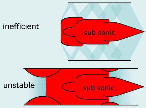
Supersonic inlets: Normal shock is not isentroph
For aircraft travelling at supersonic speeds, a design complexity arises, since the air ingested by the engine must be below supersonic speed, otherwise the engine will "choke" and cease working. This subsonic air speed is achieved by passing the approaching air through a deliberately generated shock wave (since one characteristic of a shock wave is that the air flowing through it is slowed). Therefore, some means is needed to create a shockwave ahead of the intake.
The earliest types of supersonic aircraft featured a central shock cone, called an inlet cone, which was used to form the shock wave. This type of shock cone is clearly seen on the English Electric Lightning and MiG-21 aircraft, for example. The same approach can be used for air intakes mounted at the side of the fuselage, where a half cone serves the same purpose with a semicircular air intake, as seen on the F-104 Starfighter and BAC TSR-2. A more sophisticated approach is to angle the intake so that one of its edges forms a leading blade. A shockwave will form at this blade, and the air ingested by the engine will be behind the shockwave and hence subsonic. The Century series of US jets featured a number of variations on this approach, usually with the leading blade at the outer vertical edge of the intake which was then angled back inwards towards the fuselage. Typical examples include the Republic F-105 Thunderchief and F-4 Phantom.
Later this evolved so that the leading edge was at the top horizontal edge rather than the outer vertical edge, with a pronounced angle downwards and rearwards. This approach simplified the construction of the intakes and permitted the use of variable ramps to control the airflow into the engine. Most designs since the early 1960s now feature this style of intake, for example the F-14 Tomcat, Panavia Tornado and the Concorde.
SR 71[]
In one unusual instance (the SR-71), a variable air intake design was used to convert the engine from a turbojet to a ramjet, in flight. To get good efficiency over a wide range of speeds the Pratt & Whitney J58 could move a conical spike fore and aft within the engine nacelle, to keep the supersonic shock wave just in front of the inlet. In this manner, the airflow behind the shock wave, and more importantly, through the engine, was kept subsonic at all times. At high mach, the compressor for the J58 was unable to carry the high air flow entering the inlet without stalling its blades, and so the engine directed the excess air through 6 bypass pipes straight to the afterburner. At high speeds the engine actually obtained 80% of its thrust, versus 20% through the turbines itself, in this way. Essentially, this allowed the engine to operate as a ramjet, actually improving specific impulse (fuel efficiency) by 10%–15%.
Heat exchangers[]
For engines that may need to operate at almost hypersonic speeds (mach 0 to 6), there is strong theoretical and experimental support for using a heat-exchanger to cool the air at the intake. This can increase the density of the air and thus reduce the necessary compression. The lower temperatures also permit lighter alloys to be used hence reducing the engine's weight by several times. This leads to plausible designs like SABRE, ATREX that might permit jet engined vehicles to be used to launch into space.
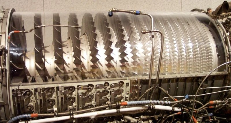

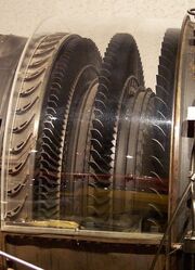
Compressor stage GE J79
Compressors[]
Each design of compressor has an operating map or characteristic peculiar to that unit. At a given throttle condition, the compressor operates somewhere along the steady state running line. Unfortunately, this operating line is displaced during transients and under extreme conditions can cross the surge or stall line (see compressor map), causing, in some cases, the compressor flow to reverse direction violently. Many compressors are fitted with variable geometry to decrease the likelihood of surge. Another ploy is to split the compressor into two or more units, operating on separate concentric shafts.
Another design consideration is the average stage loading. This can be kept at a sensible level either by increasing the number of compression stages (more weight/cost) or the mean blade speed (more blade/disc stress).
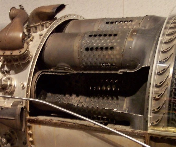

Combustion chamber GE J79
Combustors[]
Care must be taken to keep the flame burning in a moderately fast moving airstream, at all throttle conditions, as efficiently as possible. Since the turbine cannot withstand stoichiometric temperatures, resulting from the optimum combustion process, some of the compressor air is used to quench the exit temperature of the combustor to an acceptable level.
Turbines[]

Turbine Stage GE J79
Because a turbine expands from high to low pressure, there is no such thing as turbine surge or stall. Designers must, however, prevent the turbine blades and vanes from melting in a very high temperature and stress environment. Consequently bleed air extracted from the compression system is often used to cool the turbine blades/vanes internally. Other solutions are improved materials and/or special insulating coatings.
The discs must be specially shaped to withstand the huge stresses imposed by the rotating blades. Improved materials help to keep disc weight down.
Nozzles[]
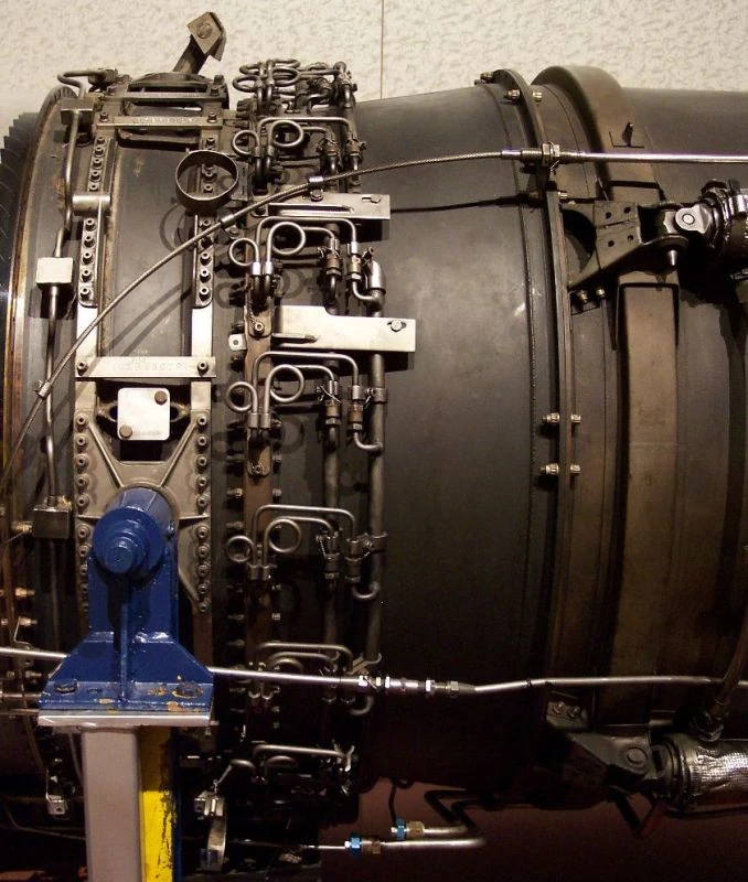
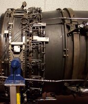
Afterburner GE J79
Most jet engines use a simple convergent nozzle, which is relatively easy to design.
However, afterburning engines require a variable area nozzle, to maintain sensible engine matching when the afterburner is alight. This is usually accommodated by using a series of interlocking petals (driven by pneumatic or hydraulic rams) to adjust the throat area.
Even more complexity is introduced if a convergent-divergent nozzle is fitted, especially if the throat and exit areas are adjusted independently.
Rocket motors also employ convergent-divergent nozzles, but these are usually of fixed geometry, to minimize weight. Because of the much higher nozzle pressure ratios experienced, rocket motor con-di nozzles have a much greater area ratio (exit/throat) than those fitted to jet engines.
At the other extreme, some high bypass ratio civil turbofans use an extremely low area ratio (less than 1.01 area ratio), convergent-divergent, nozzle on the bypass (or mixed exhaust) stream, to control the fan working line. The nozzle acts as if it has variable geometry. At low flight speeds the nozzle is unchoked (less than a Mach number of unity), so the exhaust gas speeds up as it approaches the throat and then slows down slightly as it reaches the divergent section. Consequently, the nozzle exit area controls the fan match and, being larger than the throat, pulls the fan working line slightly away from surge. At higher flight speeds, the ram rise in the intake increases nozzle pressure ratio to the point where the throat becomes choked (M=1.0). Under these circumstances, the throat area dictates the fan match and being smaller than the exit pushes the fan working line slightly towards surge. This is not a problem, since fan surge margin is much better at high flight speeds.
Engine Performance[]
TS Diagram[]
Temperature vs Entropy diagrams (see example, right) are usually used to illustrate the cycle of gas turbine engines. All the reader really needs to know about entropy is that it represents the degree of disorder of the molecules in the fluid and that it tends to increase!
Apart from stations 0 and 8s, stagnation pressure and stagnation temperature are used. Station 0 is ambient.
The processes depicted are:
- Freestream (stations 0 to 1)
- In the example, the aircraft is stationary, so stations 0 and 1 are coincident.
- Station 1 is not depicted on the diagram.
- Intake (stations 1 to 2)
- In the example, a 100% intake pressure recovery is assumed, so stations 1 and 2 are coincident.
- Compression (stations 2 to 3)
- The ideal process would appear vertical on a TS diagram. In the real process there
- is friction, turbulence and, possibly, shock losses, making the exit temperature, for
- a given pressure ratio, higher than ideal. The shallower the positive slope on the
- TS diagram, the less efficient the compression process.
- Combustion (stations 3 to 4)
- Heat (usually by burning fuel) is added, raising the temperature of the fluid.
- There is an associated pressure loss, some of which is unavoidable
- Turbine (stations 4 to 5)
- The temperature rise in the compressor dictates that there will be an associated
- temperature drop across the turbine. Ideally the process would be vertical on a
- TS diagram. However, in the real process, friction and turbulence cause the pressure drop
- to be greater than ideal. The shallower the negative slope on the TS diagram, the less efficient
- the expansion process.
- Jetpipe (stations 5 to 8)
- In the example the jetpipe is very short, so there is no pressure loss. Consequently, stations 5
- and 8 are coincident on the TS diagram.
- Nozzle (stations 8 to 8s)
- These two stations are both at the throat of the (convergent) nozzle. Station 8s represents static
- conditions. Not shown on the TS diagram is the expansion process, external to the nozzle, down
- to ambient pressure.
Design Point Performance Equations[]
In theory, any combination of flight condition/throttle setting can be nominated as the engine performance Design Point. Usually, however, the Design Point corresponds to the highest corrected flow at inlet to the compression system (e.g. Take-off Rating, Sea Level Static, ISA)
The design point net thrust of any jet engine can be estimated by working through the engine cycle, step by step. Below are the equations for a single spool turbojet.
Freestream


Intake


Compressor


Combustor


Turbine
Equating the turbine and compressor powers, we have:

A simplyfying assumption sometimes made is for the addition of fuel flow to be exactly offset by an overboard compressor bleed, so mass flow remains constant throughout the cycle.

Jetpipe


Nozzle


Gross Thrust

Ram Drag

Net Thrust

Note that mass flow is the sizing parameter: doubling the airflow, doubles the thrust.
Note:
- A flow area
- Cpc specific heat at constant pressure for air
- Cpt specific heat at constant pressure for combustion products
- Cx thrust coefficient
- g acceleration of gravity
- J mechanical equivalent of heat
- M flight Mach number
- p static pressure
- P total pressure
- prf intake pressure recovery factor
- R gas constant
- RIT (turbine) rotor inlet temperature
- t static temperature
- T total temperature
- V velocity
- w mass flow
- ρ density
- γc ratio of specific heats for air
- γt ratio of specific heats for combustion products
- ηpc compressor polytropic efficiency
- ηpt turbine polytropic efficiency
Off-Design[]
An engine is said to be running Off-Design if any of the following apply:
a) change of throttle setting
b) change of altitude
c) change of flight speed
d) change of climate
e) change of installation (e.g. customer bleed or power off-take)
Although each Off-Design point is effectively a design point calculation, the resulting cycle (normally) has the same turbine and nozzle geometry as that at the engine Design Point. Obviously the final nozzle cannot be over or under-filled with flow. This rule also applies to the turbine nozzle guide vanes, which act like small nozzles.
Design point calculations are normally done by a computer program. By the addition of an iterative loop, such a program can also be used to create a crude off-design model.
The variables for the single spool turbojet iteration would typically be:
RIT (or some other function of fuel flow), w2, P3/P2
Typically, the constraints imposed would be:
Engine match (e.g. Fn , fuel flow, etc), A8geometric, w4corrected
The latter two are the physical constraints that must be met.
Corrected flow is the flow that would pass through a device, if the entry pressure and temperature corresponded to ambient conditions at Sea Level on a Standard Day.
A more refined off-design model can be created using compressor maps and turbine maps to predict off-design efficiencies, relative shaft speeds, etc.
The nominal net thrust quoted for a jet engine usually refers to the Sea Level Static (SLS) condition, either for the International Standard Atmosphere (ISA) or a hot day condition (e.g. ISA+10C). As an example, the GE90-76B has a Take-off static thrust of 76000 lbf at SLS, ISA+15C.
Naturally, net thrust will decrease with altitude, because of the lower density. There is also, however, a flight speed effect.
Initially as the aircraft gains speed down the runway, there will be little increase in nozzle pressure and temperature, because the ram rise in the intake is very small. There will also be little change in mass flow. Consequently, nozzle gross thrust initially only increases marginally with flight speed. However, being an air breathing engine (unlike a conventional rocket) there is a penalty for taking on-board air from the atmosphere. This is known as ram drag. Although the penalty is zero at static conditions, it rapidly increases with flight speed causing the net thrust to be eroded.
As flight speed builds up after Take-off, the ram rise in the intake starts to have a significant effect upon nozzle pressure/temperature and intake airflow, causing nozzle gross thrust to climb more rapidly. This term now starts to offset the still increasing ram drag, eventually causing net thrust to start to increase. In some engines, the net thrust at say Mach 1.0, Sea Level can even be slightly greater than the static thrust. Above Mach 1.0, with a subsonic inlet design, shock losses tend to decrease net thrust, however a suitably designed supersonic inlet can give a subsonic airspeed entering the compressor, whilst giving a useful compression, and thus net thrust and efficiency can continue to climb.
The thrust lapse described above depends on the design specific thrust and, to a certain extent, on how the engine is rated with intake temperature.
See also[]
- Jet aircraft
- Jetboat
- Spacecraft propulsion
- Supercharger
- Turbocharger
- Gas turbine
External links[]
- RMCybernetics - A simple Homemade Jet Engine
- Journey through a jet engine(flash)
- How Stuff Works article on how a Gas Turbine Engine works
- Influence of the Jet Engine on the Aerospace Industry
- An Overview of Military Jet Engine History (Rand Corp., 24 pgs, PDF)
| This page uses Creative Commons Licensed content from Wikipedia (view authors). | 
|