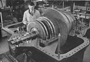
WWII era steam turbine used for ship propulsion.
Gas turbine
A turbine is a rotary engine that extracts energy from a fluid flow. Claude Burdin coined the term from the Latin turbinis, or vortex, during an 1828 engineering competition.
Parts[]
The simplest turbines have one moving part, a rotor assembly, which is a shaft with blades attached. Moving fluid acts on the blades, or the blades react to the flow, so that they rotate and impart energy to the rotor.
Gas, steam, and water turbines usually have a casing around the blades that focuses and controls the fluid. The casing and blades may have variable geometry that allows efficient operation for a range of fluid-flow conditions.
Examples[]
Early turbine examples are windmills and water wheels.
Turbines types[]
A turbine operating in reverse is called a compressor or turbopump. It converts mechanical energy to fluid energy (flow).
Theory of operation[]
A working fluid contains potential energy (pressure head) and kinetic energy (velocity head). The fluid may be compressible or non-compressible. Several physical principles are employed by turbines to collect this energy—
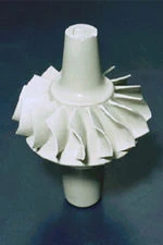
Silicon nitride turbine wheel for use in small turbogenerators
Impulse turbines change the direction of flow of a high velocity fluid jet. The resulting impulse spins the turbine and leaves the fluid flow with diminished kinetic energy. There is no pressure change of the fluid in the turbine rotor blades. Before reaching the turbine the fluid's Pressure head is changed to velocity head by accelerating the fluid with a nozzle. Pelton wheels and de Laval turbines use this process exclusively. Impulse turbines do not require a pressure casement around the runner since the fluid jet is prepared by a nozzle prior to reaching turbine. Newton's second law describes the transfer of energy for impulse turbines.
Reaction turbines develop torque by reacting to the fluid's pressure or weight. The pressure of the fluid changes as it passes through the turbine rotor blades. A pressure casement is needed to contain the working fluid as it acts on the turbine stage(s) or the turbine must be fully immersed in the fluid flow (wind turbines). The casing contains and directs the working fluid and, for water turbines, maintains the suction imparted by the draft tube. Francis turbines and most steam turbines use this concept. For compressible working fluids, multiple turbine stages may by used to efficiently harness the expanding gas. Newton's third law describes the transfer of energy for reaction turbines.
Turbine designs will use both these concepts to varying degrees whenever possible. Wind turbines use a foil to generate lift from the moving fluid and impart it to the rotor (this is a form of reaction), they also gain some energy from the impulse of the wind, by deflecting it at an angle. Crossflow turbines are designed as an impulse machine, with a nozzle, but in low head applications maintain some efficiency through reaction, like a traditional water wheel. Gas turbines with multiple stages have the first stage reacting to impulse of the gas flow (because it is inefficient to increase the velocity when it is almost at the speed of sound) and later stages being designed for reaction in the decreasing velocity flow. Blades in many stages being arranged to be reaction over some parts (of their length) and impulse over the rest.
Classical turbine design methods were developed in the mid 19th century. Vector analysis related the fluid flow with turbine shape and rotation. Graphical calculation methods were used at first. Formulas for the basic dimensions of turbine parts are well documented and a highly efficient machine can be reliably designed for any fluid flow condition. Some of the calculations are empirical or 'rule of thumb' formulae, and others are based on classical mechanics. As with most engineering calculations, simplifying assumptions were made.
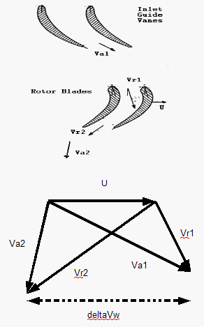
Typical velocity triangles for a single turbine stage
Velocity triangles can be used to calculate the basic performance of a turbine stage. Gas exits the stationary turbine nozzle guide vanes at absolute velocity Va1. The rotor rotates at velocity U. Relative to the rotor, the velocity of the gas as it impinges on the rotor entrance is Vr1. The gas is turned by the rotor and exits, relative to the rotor, at velocity Vr2. However, in absolute terms the rotor exit velocity is Va2. The velocity triangles are constructed using these various velocity vectors. Velocity triangles can be constructed at any section through the blading (for example: hub , tip, midsection and so on) but are usually shown at the mean stage radius. Mean performance for the stage can be calculated from the velocity triangles, at this radius, using the Euler equation:

Whence:

where: acceleration of gravity

enthalpy drop across stage

turbine entry total (or stagnation) temperature

turbine rotor peripheral velocity

delta whirl velocity

The turbine pressure ratio is a function of and the turbine efficiecy.

Modern turbine design carries the calculations further. Computational fluid dynamics dispenses with many of the simplifying assumptions used to derive classical formulas and computer software facilitates optimization. These tools have led to steady improvements in turbine design over the last forty years.
The primary numerical classification of a turbine is its specific speed. This number describes the speed of the turbine at its maximum efficiency with respect to the power and flow rate. The specific speed is derived to be independent of turbine size. Given the fluid flow conditions and the desired shaft output speed, the specific speed can be calculated and an appropriate turbine design selected.
The specific speed, along with some fundamental formulas can be used to reliably scale an existing design of known performance to a new size with corresponding performance.
Off-design performance is normally displayed as a turbine map or characteristic.
Types of turbines[]
- Steam turbine
- Gas turbine engines are sometimes referred to as turbine engines. Such engines usually feature an inlet, fan, compressor, combustor and nozzle (possibly other assemblies) in addition to one or more turbines.
- transonic turbine The gasflow in most turbines employed in gas turbine engines remains subsonic throughout the expansion process. In a transonic turbine the gasflow becomes supersonic as it exits the nozzle guide vanes, although the downstream velocities normally become subsonic. Transonic turbines operate at a higher pressure ratio than normal but are usually less efficient and uncommon.
- contra-rotating turbines Some efficiency advantage can be obtained if a downstream turbine rotates in the opposite direction to an upstream unit. However, the complication may be contraproductive.
- statorless turbine Multi-stage turbines have a set of static (meaning stationary) inlet guide vanes that direct the gasflow onto the rotating rotor blades. In a statorless turbine the gasflow exiting an upstream rotor impinges onto a downstream rotor without an intermediate set of stator vanes (that rearrange the pressure/velocity energy levels of the flow) being encountered.
- ceramic turbine Most turbine blades (and vanes) are made from nickel alloy and often require intricate air-cooling passages to prevent the metal from melting. In recent years, experimental ceramic blades have been manufactured and tested in gas turbines, with a view to increasing Rotor Inlet Temperatures and/or, possibly, eliminating aircooling. Unfortunately, like china cups, ceramic blades are very brittle and cannot withstand sudden shock. Ways of overcoming this problem are being investigated.
- shrouded turbine Many turbine rotor blades have a shroud at the top, which interlocks with that of adjacent blades, to increase damping and thereby reduce blade flutter.
- shroudedless turbine Modern practise is, where possible, to eliminate the rotor shroud, thus reducing the centrifugal load on the blade and the cooling requirements.
- Water turbine
- Wind turbine These normally operate as a single stage without nozzle and interstage guide vanes.
- Water and Wind turbines have a thermodynamic cycle that is part of weather.
Uses of turbines[]
Almost all electrical power on Earth is produced with a turbine of some type. The exceptions being solar panels, fuel cells, and diesel generators which are commonly use in small isolated towns (this practice is very common in Alaska for instance). Very high thermal efficiencies (Power Production Efficiency = [Electrical energy Output/Thermal Energy Input]) are achievable in gas turbine power generation facilities (60% or greater when using combined cycles).
Most jet engines (excluding scramjet and ramjet engines) rely on turbines to supply mechanical work from their working fluid and fuel as do all nuclear warships and power plants.
Turbines are often part of a larger machine. A Gas turbine, for example, may refer to an internal combustion machine that contains a turbine, ducts, compressor, combustor, heat-exchanger, fan and (in the case of one designed to produce electricity) an alternator.
Reciprocating engine Piston engines, especially for aircraft, can use a turbine powered by their exhaust to drive an intake-air compressor, a configuration known as a turbocharger (turbine supercharger) or, colloquially, a "turbo".
Turbines can have incredible power density (with respect to volume and weight). This is because of their ability to operate at very high speeds. The Space Shuttle main engine's use Turbopumps (a turbopump is a machine consisting of a pump driven by a turbine engine) to feed the propellants (liquid oxygen and liquid hydrogen) into the engine's combustion chamber, the liquid hydrogen turbopump is slightly larger than an automobile engine (weighing approximately 700 lb) and produces nearly 70,000 hp (52.2 MW).
External links[]
| This page uses Creative Commons Licensed content from Wikipedia (view authors). | 
|