Lift consists of the sum of all the fluid dynamic forces on a body perpendicular to the direction of the external flow around that body.
There are a number of ways of explaining the production of lift; some are more complicated than others, some have been shown to be false. The simplest explanation is that the wing deflects air downward, and the reaction pushes the wing up. More complicated explanations focus on the air pressure around the wing, but these apoaches are merely different expressions of the same underlying physical principles.
Reaction due to accelerated air[]
In air (or comparably in any fluid), lift is created as an airstream passes by an airfoil and is deflected downward. The force created by this deflection of the air creates an equal and opposite force upward on an airfoil according to Newton's third law of motion. The deflection of airflow downward during the creation of lift is known as downwash.
It is important to note that the deflection of the air does not simply involve the air molecules "bouncing off" the bottom of the airfoil. Rather, air molecules closely follow both the top and bottom surfaces of the airfoil, and so the airflow is deflected downward by both the upper and lower surfaces. The downward deflection during the creation of lift can also be described as a "turning" of the airflow.
Nearly any shape will produce lift if curved or tilted with respect to the air flow direction. However, most shapes will be very inefficient and create a great deal of drag. One of the primary goals of airfoil design is to devise a shape that produces the most lift while producing the least lift-induced drag.
The airflow normally follows the curvature of the wing surface as it changes direction - this is known as flow-attachment, also called the Coanda effect.
It is possible to measure lift using the reaction model. The force acting on the airfoil is the negative of the time-rate-of-change of the momentum of the air. In a wind tunnel, the speed and direction of the air can be measured (using, for example, a Pitot tube or Laser Doppler velocimetry) and thence the lift derived.
Bernoulli's principle[]
The force on the wing can also be examined in terms of the pressure differences above and below the wing. (This method of explanation is mathematically equivalent to the Newton's 3rd law explanation as developed above.) The relationship between the velocities and pressures above and below the wing are nearly predicted by Bernoulli's equation.
More generally, the resulting force (Lift + Drag) is the integral of pressure on the contour of the wing.

where:
- L is the Lift,
- D is the Drag,
- is the frontier of the domain,
- p is the value of the pressure,
- n is the normal to the profile.

If the velocity of the fluid at each point is known, Bernoulli's law can be applied to determine the pressure:

where:
- v is the velocity of the fluid
- p is the pressure
- is the density

Thus, Bernoulli's law allows v to be substituted for p in the integral to compute the total aerodynamic force, and the resulting equation suffices to predict both lift and drag. However it assumes an a priori knowlege of the velocity vector field in the vicinity of the wing; in particular Bernoulli's law does not explain why the air speeds up or slows down near the wing.
Also, Bernoulli's law makes assumptions on the flow, some of which may be not be applicable in all situations. In particular, the simple form above ignores compressibility. For compressible flow, a more complicated form of Bernoulli's law needs to be applied.
Circulation[]
A third way of calculating lift is a mathematical construction called circulation. Again, it is mathematically equivalent to the two explanations above. It is often used by practicing aerodynamicists as a convenient quantity, but is not often useful for a layperson's understanding. The circulation is the line integral of the velocity of the air, in a closed loop around the boundary of an airfoil. It can be understood as the total amount of "spinning" (or vorticity) of air around the airfoil. When the circulation is known, the section lift can be calculated using:

where
is the air density, is the free-stream airspeed, and is the circulation.


The Helmholtz theorem states that circulation is conserved. When an aircraft is at rest, there is no circulation. As the flow speed increases (that is, the aircraft accelerates in the air-body-fixed frame), a vortex, called the starting vortex, forms at the trailing edge of the airfoil, due to viscous effects in the boundary layer. Eventually the vortex detaches from the airfoil and gets swept away from it rearward. The circulation in the starting vortex is equal in magnitude and opposite in direction to the circulation around the airfoil. Theoretically, the starting vortex remains connected to the vortex bound in the airfoil, through the wing-tip vortices, forming a closed circuit. In reality the starting vortex gets dissipated by a number of effects, as do the wing-tip vortices far behind the aircraft.
Coefficient of lift[]
Aerodynamicists are one of the most frequent users of dimensionless numbers. The coefficient of lift is one such term. When the coefficient of lift is known, for instance from tables of airfoil data, lift can be calculated using the Lift Equation:

where:
- is the coefficient of lift,
- is the density of air (1.225 kg/m3 at sea level)*
- V is the freestream velocity, that is the airspeed far from the lifting surface
- A is the surface area of the lifting surface
- L is the lift force produced.

This equation can be used in any consistent system. For instance, if the density is measured in kilograms per cubic metre, the velocity is measured in metres per second, and the area is measured in square metres, the lift will be calculated in newtons. Or, if the density is in slugs per cubic foot, the velocity is in feet per second, and the area is in square feet, the resulting lift will be in pounds force.
* Note that at altitudes other than sea level, the density can be found using the Barometric formula
Compare with: Drag equation.
Common explanation of lift is false[]
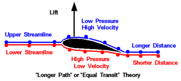
An illustration of the (incorrect) equal transit-time theory.
There is a common explanation put forward in many mainstream sources that explains lift as follows: due to the greater curvature (and hence longer path) of the upper surface of an aerofoil, the air going over the top must go faster in order to "keep up" with the air flowing around the bottom since they have to both traverse the airfoil in the same amount of time. Bernoulli's law is then cited to say that due to the faster speed on top the pressure is lower. Despite the fact that this "explanation" is probably the most common of all, it is false. There is no physical principle that implies the air over the top must keep up with the air below, and expiremental evidence shows that it does not.
Such an explanation would mean that an aircraft could not fly inverted, which is demonstrably not the case. It also fails to account for aerofoils which are fully symmetrical yet still develop significant lift, or for sails which are thin membranes with no path-length difference between their two sides.
Although the assumption of equal transit time is not correct, some of the phenomena described by this explanation are. In particular:
- there are regions of low pressure above the wing and regions of high pressure below the wing
- the air speeds up as it passes over the top of the wing and slows down as it passes the bottom, and
- Bernoulli's law can be used to relate the velocities and pressures.
However, Bernoulli's law does not explain why the air changes speed, it only says that speed and pressure are related. Without some reason why the air changes speed, any explanation based on speed differences is incomplete (and of course any explanation that incorrectly describes why the speed is different is itself incorrect) .
Note that while this explanation depends on Bernoulli's law, the fact that this theory has been discredited does not imply that Bernoulli's law is incorrect.
It is interesting to note that Albert Einstein, in attempting to design a practical aircraft based on this principle, came up with an aerofoil section that featured a large hump on its upper surface, on the basis that an even longer path must aid lift if the principle is true. Its performance was terrible, and we can suppose that in fact this was the point that Einstein was trying to prove.
There is a book on this topic: "Understanding Flight", published by McGraw-Hill, [[ISBN 0071363777]], by David Anderson and Scott Eberhardt. The authors are a physicist and an aeronautical engineer. They explain flight in non-technical terms and specifically address the Bernoulli myth.
Although currently accepted theories of aerodynamic lift were developed as early as 1907, this incorrect explanation didn't appear until 1936 and became popularized later, especially after World War II. It is unclear why this explanation has gained such currency, except by repetition and perhaps the fact that it is easy to grasp intuitively without mathematics and gets some of the description right. Note that this explanation does not appear in peer-reviewed papers (except when the author points it out as incorrect) and any text book claiming to be a serious work on the topic will not promote this explanation.
External links[]
- How Airplanes Fly: A Physical Description of Lift
- NASA tutorial, with animation, describing lift
- Beginners intro to why and how model planes fly
- Explanation of Lift with animation of fluid flow around an airfoil
- An Excellent treatment of why and how wings generate lift
| This page uses Creative Commons Licensed content from Wikipedia (view authors). | 
|