Steam locomotive nomenclature is a listing of the components found on a Steam Locomotive.
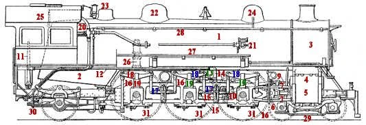
Fig. 1: Steam Locomotive
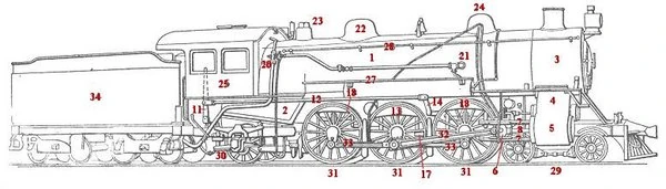
Fig. 2: Steam Locomotive and Tender
The following components appear on the illustrations shown above.
- Boiler — A water container that is brought to a boil by hot gases passed through long tubes, thereby producing steam. From time to time the tubes need to be cleaned as they accumulate soot. The smoke box cover at the front of the locomotive is bolted on so that it can be removed for access for cleaning the tubes. Because of the high steam demands, locomotive boilers typically have very high heating surface to grate area ratios, commonly 75:1 or greater.
- Firebox — A box-like furnace chamber that is built into the boiler and usually surrounded by water to contain the fire that is used to heat the boiler. Early locomotives used wood for fuel, whereas later locomotives used coal or oil. With each change in fuel, different types of firebox have been built including the Wootten, which is very wide and shallow to burn poor grades of coal, the Belpair, which has a flat crown sheet and deep legs surrounded by water jackets. This Belpair type was used extensively in British locomotives and in machines built by the Pennsylvania Railway in America.
- Smoke box — The drum which draws through hot gases by means of a partial vacuum produced by a venturi effect created by channeling exhaust gases, further heating the boiler. When the locomotive is not moving, a ring of steam jets around the exhaust nozzle can be opened to produce a small artificial draft.
- Valve chest — A smaller cylinder above the main cylinder containing passageways used by the valves to distribute live steam to the cylinders.
- Cylinder — A hollow device that converts steam energy into mechanical energy.
- Cross head — A sliding hinge which guides and supports the end of the piston rod and provides a connection of the rod to the main rod.
- Crosshead guides — These guide the cross head and take the thrust produced from the reciprocating to rotary motion conversion. Also known as slide bars.
- Piston rod — A rod that connects the piston in the cylinder to the cross-head axle.
- Valve stem — A rod attached to the valve for moving it during engine operation.
- Link
- Reverse lever — A lever within the cab that controls the direction of travel and the timing of the valve. Also called a "johnson bar".
- Reach rod — This rod links the reversing actuator with the valve gear.
- Tumbling shaft
- Rocker arm
- Eccentric rod
- Frame — The steel beams that provide support for the cab, fire box, boiler and smoke box.
- Equalizing levers or bars This is a lever free to pivot about its center which is firmly affixed to the locomotive frame. The free ends of the lever are connected to the leaf springs associated with each wheel.
- Springs A built up leaf spring is located typically above, and sometimes below each drive wheel. These are connected at their middle to the journal box of the axle they are centered over. The ends of these springs connect to the locomotive frame either through a hanger, or through an equalizing lever or bar.
- Pedestal or saddle A link which connects the clamp ate the center of the springs to the bearing journal.
- Injector — Steam driven vacuum pumps used to inject water into the boiler under pressure.
- Boiler check valve — A check valve at the point where water enters the boiler from the injectors; used to prevent backflow.
- Steam Dome — An expansion at the top of the boiler to allow space for the heated steam to collect; the throttle valve for the locomotive is located here.
- Auxilary Steam Dome — A collection point for steam used to power locomotice appliances such as the generator turbine, air compressor pumps, and steam lubricators.
- Sand box — A container for holding sand used to improve traction especially on wet or icy rails.
- Cab — A compartment from which the crew consisting of an engineer and fireman can control the engine and feed or look after the fire box.
- Air pump — A pump to provide air pressure for keeping the brakes released. A loss in air pressure causes the brakes to be applied.
- Foot board — A walkway along the locomotive to facilitate inspection and maintenance.
- Hand rail — A railing above the foot board used for support while walking along the foot board.
- Pilot truck1 — Wheels at the front that helped guide the locomotive. Some locomotives did not have a pilot truck.
- Trailing truck1 — Wheels at the rear of the locomotive to help support the weight of the cab and fire box. Some locomotives did not have a trailing truck.
- Drivers1 — The wheels that deliver locomotive power to the rails. The drivers are weighted so that the center of gravity of the drivers and rods coincides with the center of rotation.
- Main rod — A steel arm that converts the horizontal motion of the piston into a rotation motion of the Driver. Also called the connecting rod.
- Side rods
- Tender — A container that holds both water for the boiler and combustible fuel such as wood, coal or oil for the fire box.
Notes:
- Locomotives are classified by the number of wheels on the pilot truck, followed by the number of driving wheels, followed by the number of wheels on the trailing truck. Thus the locomotive pictured above would be classified as a 4-6-2 locomotive. This system is known as Whyte notation.
Additional parts or components of a locomotive:
- Air hose — A hose for supplying air pressure to release the brakes on the rail cars. A hose is located next to the front and rear couplers.
- Backhead — The firebox wall in the locomotive cab used for mounting the locomotive controls.
- Bell — A bell is located on top of the boiler and is used for signaling.
- Coupler — A device at the front and rear of the locomotive for connecting locomotives and rail cars together.
- Pilot — A protective guard at the front of the locomotive to push aside obstructions.
- Feed water heater — An optional routing of the feed water piping below the smoke box to heat the water before it enters the boiler.
- Fire box door — A door to the fire box is located in the cab to allow access for the tossing of wood or the shoveling of coal and for lighting of the fire.
- Gauges — A steam pressure gauge and a water level gauge are located in the cab.
- Headlight — A lamp at the top of and in front of the smoke box to provide visibility.
- Smokestack — A short chimney on top of the smoke box to carry away the smoke.
- Whistle — A steam whistle is located on top of the boiler and is used for signaling and as a warning device.
| This page uses Creative Commons Licensed content from Wikipedia (view authors). | 
|