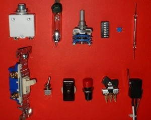
Electrical switches. Top, left to right: circuit breaker, mercury switch, wafer switch, DIP switch, surface mount switch, reed switch. Bottom, left to right: wall switch (U.S. style), miniature toggle switch, in-line switch, push-button switch, rocker switch, microswitch.
A switch is a device for changing the course (or flow) of a circuit. The term "switch" typically refers to electrical power or electronic telecommunication circuits.
In applications where multiple switching options are required, (i.e. a telephone service) mechanical switches have long been replaced by electronic variants which can be intelligently controlled and automated.
Prototype[]
The prototypical model is a mechanical device (for example a railroad switch) which can be disconnected from one course and connected to another.
Different areas[]
In electronics[]
The switch is referred to as a "gate" when abstracted to mathematical form. In the philosophy of logic, operational arguments are represented as logic gates. The use of electronic gates to function as a system of logical gates is the fundamental basis for the computer —ie. a computer is a system of electronic switches which function as logical gates.
In mechanical engineering[]
Construction[]
In the simplest case, a switch has two pieces of metal [1] called contacts that touch to make a circuit, and separate to break the circuit. The contact material is chosen for its resistance to corrosion, because most metals form insulator [2] oxides [3] that would prevent the switch from working. Sometimes the contacts are plated with noble metals [4]. They may be designed to wipe against each other to clean off any contamination. Nonmetallic conductors, such as conductive plastic [5], are sometimes used. The moving part that applies the operating force to the contacts is called the actuator, and may be a toggle or dolly, a rocker, a push-button or any type of mechanical linkage (see photo).
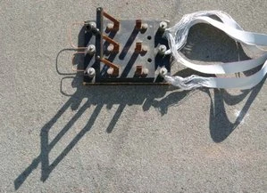
Triple Pole Single Throw (TPST) switch used to short the windings of a 3 phase wind turbine for braking purposes. Here the switch is shown in the open position.
A pair of contacts is said to be 'closed' when there is no space between them, allowing electricity to flow from one to the other. When the contacts are separated by a space, they are said to be 'open', and no electricity can flow.
Classification[]
Switches can be classified according to the arrangement of their contacts. Some contacts are normally open until closed by operation of the switch, while others are normally closed and opened by the switch action. A switch with both types of contact is called a changeover switch.
The terms pole and throw are used to describe switch contacts. A pole is a set of contacts that belong to a single circuit. A throw is one of two or more positions that the switch can adopt. In mains wiring names generally involving the word way are used; however, these terms differ between British English [6] and American English [7]. The terms two way and three way are used in both with different meanings.
| Electronics abbreviation | Expansion of abbreviation | British mains wiring name | American mains wiring name | Description | Symbol |
|---|---|---|---|---|---|
| SPST | Single pole, single throw | One way | Two way | A simple on-off switch: The two terminals are either connected together or not connected to anything. An example is a light switch. | |
| SPDT | Single pole, double throw | Two way | Three way | A simple changeover switch: C (Common) is connected to L1 or to L2. | 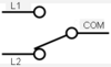
|
| SPCO | Single pole changeover or Single pole, centre off |
Equivalent to SPDT. Some suppliers use SPCO for switches with a stable off position in the centre and SPDT for those without. | |||
| DPST | Double pole, single throw | Double pole | Double pole | Equivalent to two SPST switches controlled by a single mechanism | 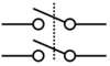
|
| DPDT | Double pole, double throw | Equivalent to two SPDT switches controlled by a single mechanism: A is connected to B and D to E, or B is connected to C and E to F. | 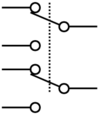
| ||
| DPCO | Double pole changeover or Double pole, centre off |
Equivalent to DPDT. Some suppliers use DPCO for switches with a stable off position in the centre and DPDT for those without. | |||
| Intermediate switch | 4-way switch | DPDT switch internally wired for polarity-reversal applications: only four rather than six wires are brought outside the switch housing; with the above, B is connected to F and C to E; hence A is connected to B and D to C, or A is connected to C and D to B. | 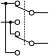
|
Switches with larger numbers of poles or throws can be described by replacing the "S" or "D" with a number or in some cases the letter T (for triple). In the rest of this article the terms SPST SPDT and intermediate will be used to avoid the ambiguity in the use of the word "way".
Make-before-break, break-before-make[]
In a multi-throw switch, there are two possible transient behaviors as you move from one position to another. In some switch designs, the new contact is made before the old contact is broken. This is known as make-before-break, and ensures that the moving contact never sees an open circuit. The alternative is break-before-make, where the old contact is broken before the new one is made. This ensures that the two contacts are never shorted to each other. Both types of design are in common use, for different applications.
Biased switches[]
A biased switch is one containing a spring that returns the actuator to a certain position. The "on-off" notation can be modified by placing parentheses around all positions other than the resting position. For example, an (on)-off-(on) switch can be switched on by moving the actuator in either direction away from the centre, but returns to the central off position when the actuator is released.
The momentary push-button switch is a type of biased switch. The most common type is a push-to-make switch, which makes contact when the button is pressed and breaks when the button is released. A push-to-break switch, on the other hand, breaks contact when the button is pressed and makes contact when it is released. An example of a push-to-break switch is a button used to release a door held open by an electromagnet. Changeover push button switches do exist but are even less common.
Special types[]
Switches can be designed to respond to any type of mechanical stimulus: for example, vibration (the trembler switch), tilt, air pressure, fluid level (the float switch), the turning of a key (key switch), linear or rotary movement (the limit switch or microswitch), or presence of a magnetic field (the reed switch).
The mercury switch consists of a blob of mercury inside a glass bulb. The two contacts pass through the glass, and are shorted together when the bulb is tilted to make the mercury roll on to them. The advantage of this type of switch is that the liquid metal flows around particles of dirt and debris that might otherwise prevent the contacts of a conventional switch from closing.
Other types of switch include:
- centrifugal switch
- DIP switch
- Hall-effect switch
- toggle switch
- Transfer switch
Intermediate switches[]
A DPDT switch has six connections, but since polarity reversal is a very common usage of DPDT switches, some variations of the DPDT switch are internally wired specifically for polarity reversal. They only have four terminals rather than six. Two of the terminals are inputs and two are outputs. When connected to a battery or other DC source, the 4-way switch selects from either normal or reversed polarity. Intermediate switches are also an important part of multiway switching systems with more than two switches (see next section).
Multiway switching[]
Multiway switching is a method of connecting switches in groups so that any switch can be used to connect or disconnect the load. This is most commonly done with lighting.
Two location switches[]
1. First method
2. Second method
3. Labelling of switch terminals
Switching a load on or off from two locations (for instance, turning a light on or off from either end of a flight of stairs) requires two SPDT switches. There are two basic methods of wiring to achieve this.
In the first method, mains is fed into the common terminal of one of the switches; the switches are then connected through the L1 and L2 terminals (swapping the L1 and L2 terminals will just make the switches work the other way round), and finally a feed to the light is taken from the common of the second switch. A connects to B or C, D connects to B or C; the light is on if A connects to D, i.e. if A and D both connect to B or both connect to C.
The second method is to join the three terminals of one switch to the corresponding terminals on the other switch and take the incoming supply and the wire out to the light to the L1 and L2 terminals. Through one switch A connects to B or C, through the other also to B or C; the light is on if B connects to C, i.e. if A connects to B with one switch and to C with the other.
Wiring needed in addition to the mains network (not including protective earths):
First method:
- double wire between both switches
- single wire from one switch to the mains
- single wire from the other switch to the load
- single wire from the load to the mains
Second method:
- triple wire between both switches
- single wire from any position between the two switches, to the mains
- single wire from any position between the two switches, to the load
- single wire from the load to the mains
If the mains and the load are connected to the system of switches at one of them, then in both methods we need three wires between the two switches. In the first method one of the three wires just has to pass through the switch, which tends to be less convenient than being connected. When multiple wires come to a terminal they can often all be put directly in the terminal. When wires need to be joined without going to a terminal a crimped joint, piece of terminal block, wirenut or similar device must be used and the bulk of this may require use of a deeper backbox.
More than two location switches[]
Three-way switching.
1. First method
2. Second method
3. Labelling of switch terminals
For more than two locations, the two cores connecting the L1 and L2 of the switches must be passed through an intermediate switch (as explained above) wired to swap them over. Any number of intermediate switches can be inserted, allowing for any number of locations.
Wiring needed in addition to the mains network (not including protective earths):
- first method
- double wire along the sequence of switches
- single wire from the first switch to mains
- single wire from the last switch to the load
- single wire (neutral) from load to mains
- second method
- double wire along the sequence of switches
- single wire from first switch to last switch
- single wire from anywhere between two of the switches to the mains
- single wire from anywhere between the same two switches to the load
- single wire (neutral) from load to mains
Contact bounce[]
Contact bounce (also called chatter) is a common problem with mechanical switches and relays. Switch and relay contacts are usually made of springy metals that are forced into contact by an actuator. When the contacts strike together, their momentum and elasticity act together to cause bounce. The result is a rapidly pulsed electrical current instead of a clean transition from zero to full current. The waveform is then further modified by the parasitic inductances and capacitances in the switch and wiring, resulting in a series of damped sinusoidal oscillations. This effect is usually unnoticeable in AC mains circuits, where the bounce happens too quickly to affect most equipment.
But it causes problems in some analogue and logic circuits that are not designed to cope with oscillating voltages.
Sequential digital logic circuits are particularly vulnerable to contact bounce. The voltage waveform produced by switch bounce usually violates the amplitude and timing specifications of the logic circuit. The result is that the circuit may fail, due to problems such as metastability, race conditions, runt pulses and glitches.
Hardware debouncing[]
Special circuits called "debouncing circuits" are often used to process the voltage from a switch or relay before it is applied to the input of a sensitive circuit.
- A simple analogue debouncing circuit consists of an RC (resistor-capacitor) filter that removes fast oscillations from the signal. However, the slowly changing edge that this produces is unsuitable for triggering high-speed logic circuits, where it could cause metastability. This issue can be resolved by feeding the signal through a Schmitt trigger.
- A debouncing circuit suitable for logic circuits consists of a monostable multivibrator, a circuit that registers the first voltage pulse, produces an output pulse of fixed width, then ignores any further switch pulses until the output pulse has terminated. The circuit designer sets the monostable's pulse width to exceed the bounce time.
- If the switch or relay has changeover (also called double-throw or SPDT) contacts, then a debouncing circuit can be made by adding an SR flip-flop. One contact of the switch drives a pulse into the set input of the flip-flop, and the other contact drives a pulse into the reset input. The output of the flip-flop is a clean pulse that goes high when the switch is pushed away from its rest position, and then low when the switch is released, with no bounce.
Software debouncing[]
If the switch voltage is fed directly to the input of a microprocessor, then the software might become confused by the rapid sequence of high and low logic levels when it is expecting only a single, stable transition between "on" and "off". If debouncing circuits have not been provided, then there are software remedies that can be used. A simple algorithm is to wait for the first transition (say, 0 to 1), then ignore the input for a fixed time before sampling it again. The time delay is selected so that the switch has stopped bouncing before it is sampled again.
References[]
- Walker, PMB, Chambers Science and Technology Dictionary, Edinburgh, 1988, ISBN 0-85296-151-1 (definition of contact bounce)
See also[]
External links[]
- How to Wire a Switch (very U.S. specific)
- Various Pressure Switches (very U.S. specific)
| This page uses Creative Commons Licensed content from Wikipedia (view authors). | 
|